In the last tutorial about Electromagnetism we saw that if we bend the conductor into a single loop the current will flow in opposite directions through the loop producing a clockwise field and an anticlockwise field next to each other. The Electromagnet uses this principal by having several individual loops magnetically joined together to produce a single coil.
Electromagnets are basically coils of wire which behave like bar magnets with a distinct north and south pole when an electrical current passes through the coil. The static magnetic field produced by each individual coil loop is summed with its neighbour with the combined magnetic field concentrated like the single wire loop we looked at in the last tutorial in the centre of the coil. The resultant static magnetic field with a north pole at one end and a south pole at the other is uniform and a lot more stronger in the centre of the coil than around the exterior.
Lines of Force around an Electromagnet

The magnetic field that this produces is stretched out in a form of a bar magnet giving a distinctive north and south pole with the flux being proportional to the amount of current flowing in the coil. If additional layers of wire are wound upon the same coil with the same current flowing, the magnetic field strength will be increased.
t can be seen from this therefore that the amount of flux available in any given magnetic circuit is directly proportional to the current flowing through it and the number of turns of wire within the coil. This relationship is called Magneto Motive Force or m.m.f. and is defined as:
$$Magneto Motive Force, (m.m.f.) = I \times N ampere turns$$
Magneto Motive Force is expressed as a current, I flowing through a coil of N turns. The magnetic field strength of an electromagnet is therefore determined by the ampere turns of the coil with the more turns of wire in the coil the greater will be the strength of the magnetic field.
The Magnetic Strength of the Electromagnet
The intensity of this field around the conductor is proportional to the distance from it with the strongest point being next to the conductor and progressively getting weaker further away from the conductor. In the case of a single straight conductor, the current flowing and the distance from it are factors which govern the intensity of the field.
The formula therefore for calculating the “Magnetic Field Strength”, H sometimes called “Magnetising Force” of a long straight current carrying conductor is derived from the current flowing through it and the distance from it.
- Where:
- H – is the strength of the magnetic field in ampere-turns/metre, At/m
- N – is the number of turns of the coil
- I – is the current flowing through the coil in amps, A
- L – is the length of the coil in metres, m
Then to summarise, the strength or intensity of a coils magnetic field depends on the following factors.
- The number of turns of wire within the coil.
- The amount of current flowing in the coil.
- The type of core material.
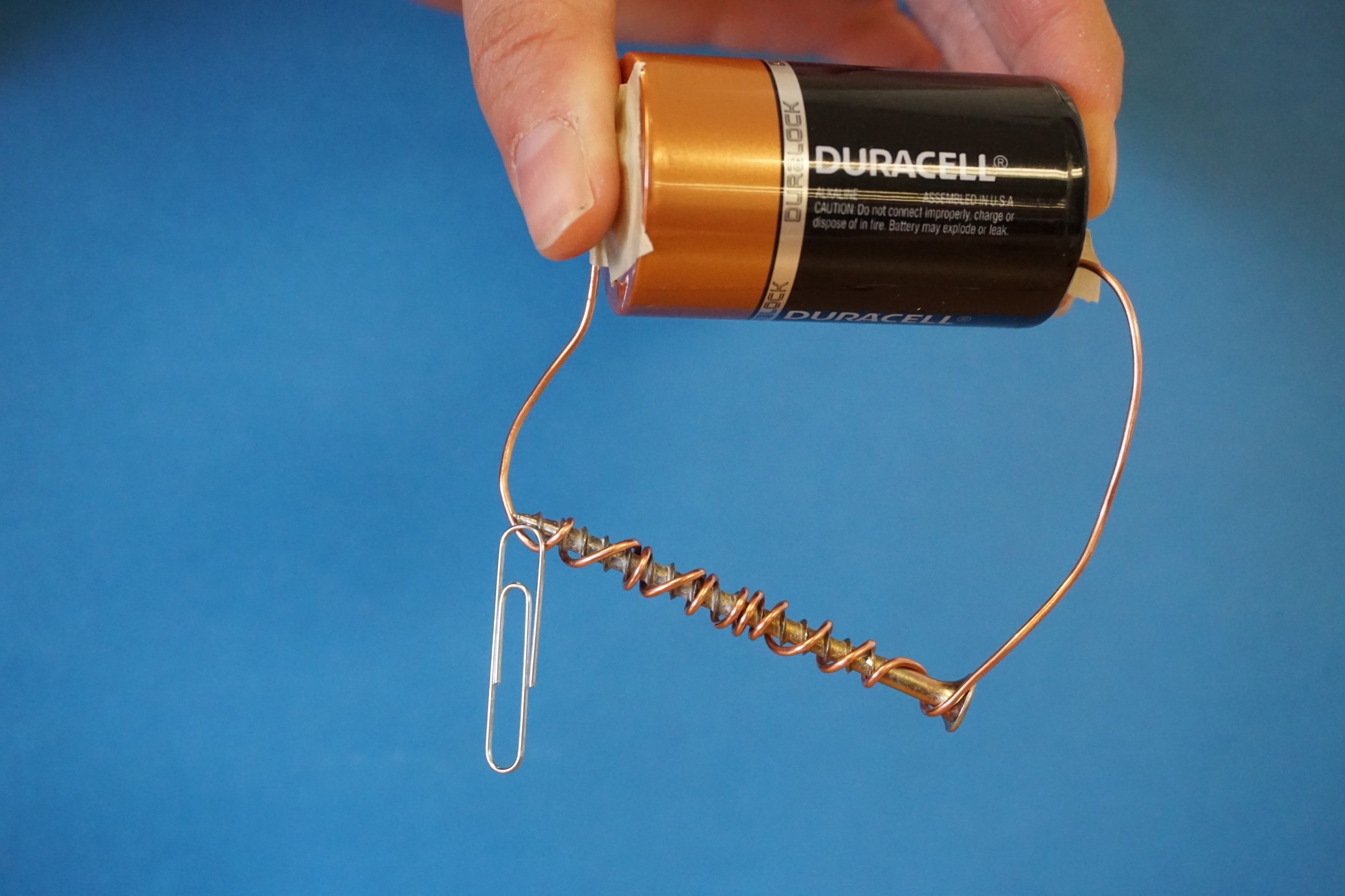
Ferromagnetic materials are those which can be magnetised and are usually made from soft iron, steel or various nickel alloys. The introduction of this type of material into a magnetic circuit has the effect of concentrating the magnetic flux making it more concentrated and dense and amplifies the magnetic field created by the current in the coil.
We can prove this by wrapping a coil of wire around a large soft-iron nail and connecting it to a battery as shown. This simple classroom experiment allows us to pick-up a large quantity of clips or pins and we can make the electromagnet stronger by adding more turns to the coil. This degree of intensity of the magnetic field either by a hollow air core or by introducing ferromagnetic materials into the core is called Magnetic Permeability.
Permeability of Electromagnets
Relative Permeability, symbol μr is the product of μ (absolute permeability) and μo the permeability of free space and is given as.
$$\mu_r = \frac{\mu}{\mu_0} = \frac{Flux Density in the Matrial}{Flux Density in a Vacuum}$$
Materials that have a permeability slightly less than that of free space (a vacuum) and have a weak, negative susceptibility to magnetic fields are said to be Diamagnetic in nature such as: water, copper, silver and gold. Those materials with a permeability slightly greater than that of free space and themselves are only slightly attracted by a magnetic field are said to be Paramagnetic in nature such as: gases, magnesium, and tantalum.
Electromagnet Example No1
The absolute permeability of a soft iron core is given as 80 milli-henries/m (80.10-3). Calculate the equivalent relative permeability value.

When ferromagnetic materials are used in the core the use of relative permeability to define the field strength gives a better idea of the strength of the magnetic field for the different types of materials used. For example, a vacuum and air have a relative permeability of one and for an iron core it is around 500, so we can say that the field strength of an iron core is 500 times stronger than an equivalent hollow air coil and this relationship is much easier to understand than 0.628×10⁻³ H/m, ( 500.4.π.10-7).
While, air may have a permeability of just one, some ferrite and permalloy materials can have a permeability of 10,000 or more. However, there are limits to the amount of magnetic field strength that can be obtained from a single coil as the core becomes heavily saturated as the magnetic flux increases
'Electronics > Electromagnetics' 카테고리의 다른 글
| Chambers in Egypt’s Great Pyramid concentrate radio waves (0) | 2022.05.01 |
|---|---|
| Electromagnetism (0) | 2022.05.01 |
| Magnetism (0) | 2022.04.30 |
| 니콜라 테슬라 평전 (0) | 2022.04.28 |
| 전자기 시대를 연, 물리학의 두 거장 패러데이와 맥스웰 (0) | 2022.04.28 |


